
Introduction
In this article, I will discuss the maintenance of aircraft engine parts, a topic I learned about during my previous internship. With this article, I aim to provide information to aspiring engineers who want to work in this sector and help them better understand their responsibilities. Although a significant amount of time has passed, I will try to put together an article using the documents I have and the research I will conduct. To understand aircraft engine maintenance, you first need to know the non-destructive test methods and measurement tools used in this field. Then, I will aim to explain the maintenance process in general terms and conclude the article. It should be noted that the maintenance process for aircraft parts can vary from part to part and engine to engine. This article will provide a general overview. I hope it will be useful for you.
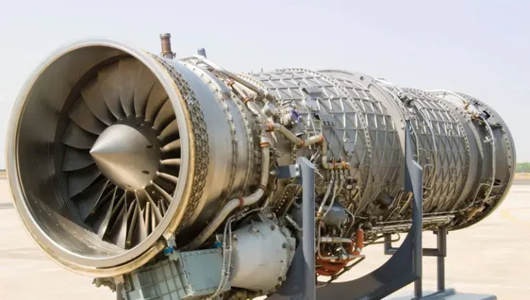
Aircraft Engine Maintenance
The aviation industry is one where maintenance protocols are extremely stringent, requiring regular inspections and servicing. Beyond the routine pre-flight checks, aircraft components must undergo scheduled maintenance after specific flight hours. The aircraft engine, being the most critical system that enables flight, comprises numerous subcomponents. Periodically, the engine must be disassembled, and each part inspected to ensure compliance with industry standards. If any part fails to meet these standards, it must either be replaced or repaired, a decision guided by the manufacturer’s manuals. The planning of the entire maintenance process is also based on these manuals. Engineers working in the maintenance field are responsible for planning the sequence of procedures, selecting appropriate measuring instruments, and overseeing the entire maintenance process for each component. It is their duty to make decisions by adhering to the manuals, especially when components fall outside the acceptable tolerances. Thus, maintenance engineers play a crucial role in ensuring that all components are in optimal condition and that safety standards are rigorously upheld.
At this point, I would like to briefly discuss the tasks I performed during my internship. We planned the maintenance processes for three different components, deciding which measurement tools to use for two different engines. Additionally, we created a document outlining the differences between the engines, highlighting factors that needed to be considered. We then compared our document with the company’s internal documentation to identify and report our shortcomings as well as those of the company. Throughout this process, I gained significant knowledge about measurement tools and non-destructive testing (NDT) methods. In the following sections, I will share what I have learned about these topics.
Measuring Instruments
To become a maintenance engineer, familiarity with measurement tools is crucial. Especially in the aviation industry, where examining damage at the micrometer level is essential, various measurement tools are required. The type of measurement tool needed can vary depending on the nature of the damage. For example, a tool used for measuring flatness cannot be used for detecting cracks. A maintenance engineer is responsible for planning the use of these tools for different measurements. The engineer must know which tool is appropriate for each type of measurement and be aware of the tool’s accuracy and error margin. Additionally, these tools need to be calibrated at regular intervals to ensure their precision and reliability. Proper calibration is vital to maintain the accuracy of measurements and the overall safety and functionality of aircraft components.
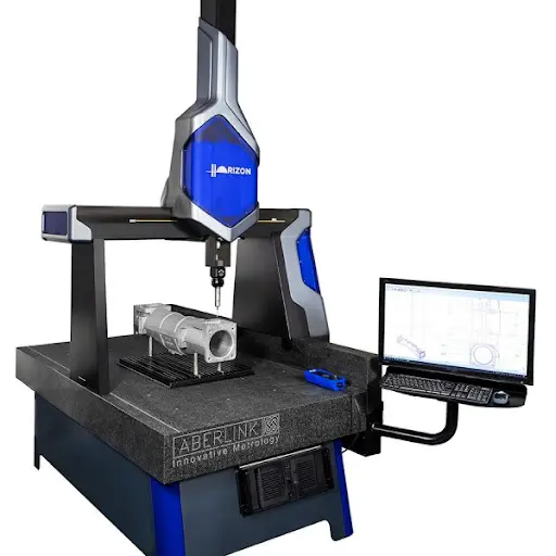
CMM (Coordinate Measuring Machine)
A Coordinate Measuring Machine (CMM) is a tool used for precise measurements with computer assistance. It uses a probe to map the x, y, and z coordinates of the points it touches, transferring this data to a software program. This enables the measurement of surface parallelism, concentricity of nested circles, and flatness. Length measurements can also be performed using a CMM. Additionally, CMMs can import CAD models, allowing measurements to be made directly from the model. However, operators can also perform manual measurements if needed. Despite its precision, the CMM has some disadvantages. Programming a CMM can take anywhere from 1 to 3 days, depending on the complexity. This makes it less suitable for single, one-time measurements, where other measurement tools might be more efficient and cost-effective. While the CMM excels in accuracy and versatility, its setup time can be a limiting factor for certain applications.
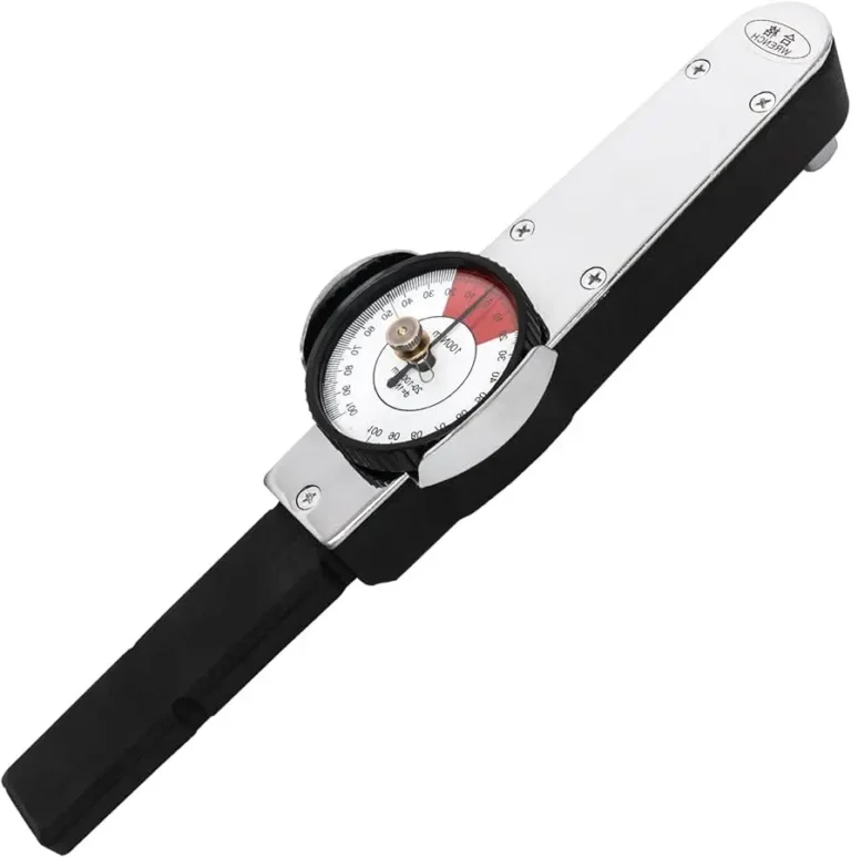
Torquemeter
A torquemeter is typically used during the assembly and disassembly processes and is seldom utilized during regular maintenance. However, it becomes essential in certain modules where intermediate assembly is required, which is why it is included in this discussion. For these modules, connection elements must be assembled step-by-step in the sequence and with the torque values specified in the manuals. The tightening process may be done incrementally to ensure the forces are evenly distributed. This is crucial to prevent any imbalance within the engine, which could otherwise lead to significant issues. Proper use of a torquemeter ensures that the components are securely and correctly fastened, maintaining the engine’s overall stability and functionality.
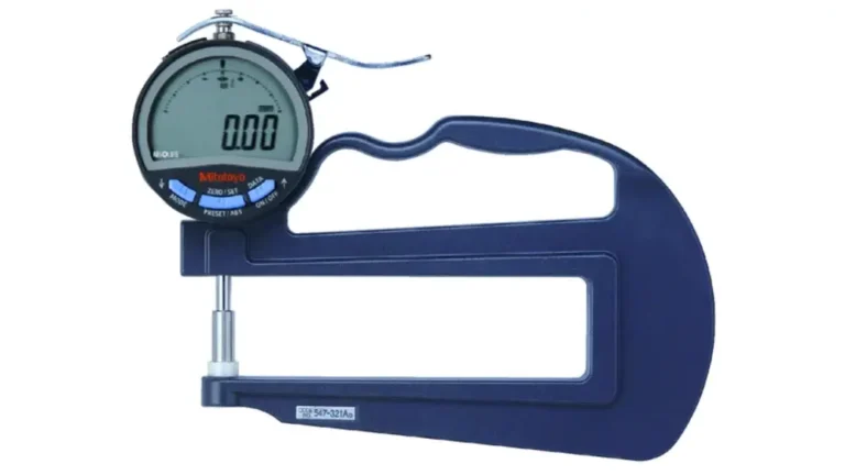
Thickness Gage
A thickness gage serves a similar function to calipers and micrometers in measuring thickness. However, these two tools often fall short when it comes to measuring the central areas of large parts. The design of the thickness gage, as shown in the photo, allows it to reach into these areas, making such measurements possible. While we used the thickness gage infrequently for the modules we examined, it proved valuable in specific situations where other tools could not reach.
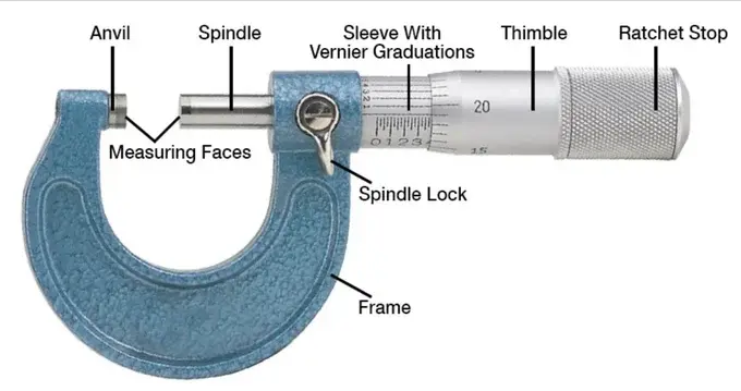
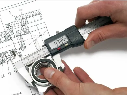
Micrometer
Micrometers are primarily divided into two types: inside micrometers and outside micrometers, and they come in various sizes. As the names suggest, they are used for measuring diameters. Calipers, on the other hand, are versatile tools used for measuring length, outside diameter, inside diameter, and depth. The measurement accuracy of micrometers is higher than that of calipers, making them the preferred choice for tasks requiring precise diameter measurements.
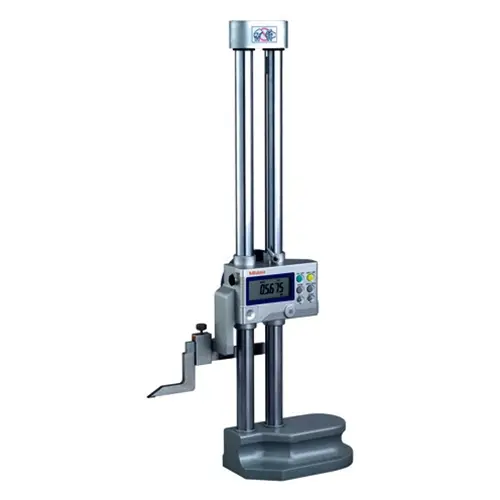
Height Gage
A height gage is used for measurements along the z-axis and is often employed for distance measurements when a CMM is not available. In addition to basic height measurements, the height gage can be used to measure flatness by placing the probe on a point on a flat surface and moving the part underneath it. However, height gages and CMM machines are generally not preferred for flatness measurements. They can be used for such purposes, but other specialized tools are typically more suitable for ensuring the precision and accuracy required for flatness evaluations.
Tracer & Optic Compressor
These tools are used for roundness and flatness measurements. The tracer works by melting a mold onto the area of the part that needs to be examined, and then mapping the surface of the mold that has taken the shape of the surface. The optical compressor functions more like a magnifying glass. You can magnify the relevant part of the module to perform these measurements.
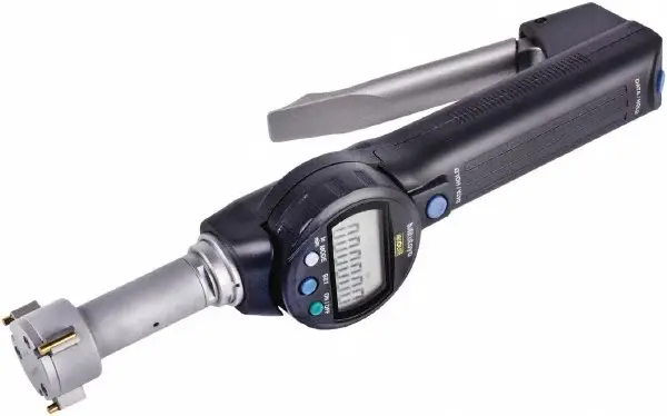
Bore gage
As expected, there are many holes in aircraft modules. These include borescope ports used solely for inspection purposes, as well as holes for nuts during assembly. Additionally, there are ports for cables to pass through. To check if these holes are within the tolerance range, a gun-shaped tool called a bore gauge is used.
Maintenance Process
In this section, I will discuss the general maintenance procedure. I will also touch on details such as damages that can be encountered in modules. I will only talk about FPI (Fluorescent Penetrant Inspection). I believe this non-destructive test method is sufficient to understand the process.
Blend
This step is not required for every module but is a common procedure. The high metal on the module’s surface is cleaned. Then, the presence of high metal is detected using FPI. If the high metal is not completely cleaned, the process is repeated. If no high metal is found, this cycle can be skipped, and the maintenance process can proceed to the next stages.
FPI
Fluorescent Penetrant Inspection (FPI) is a widely used non-destructive testing (NDT) method for detecting surface-breaking defects in non-porous materials. It is commonly used in industries such as aviation, where the detection of the smallest damages is critical. In FPI, a penetrant that glows under UV light is used. This penetrant gets trapped in surface discontinuities like cracks. The excess penetrant on the surface is cleaned, and the trapped penetrant is drawn to the surface with the help of a developer. Under UV light, the locations of these defects become visible. As mentioned earlier, the cleaning process is crucial before and after FPI to ensure a clean surface for accurate inspection. Therefore, the FPI process is often carried out as clean-FPI-clean. During the cleaning process, the part is immersed in baths containing various chemicals. It is important to consider the material of the part during this process. Manuals specify which chemicals should be used.

Visual Inspection
At this stage, the surface discontinuities that have emerged are examined. Different tools and tolerances are used for inspection based on the location and type of damage. The maintenance engineer must select the appropriate measurement tool according to the damage’s location. Manuals also provide the tolerance range for that specific area. Repair is typically valid within a certain tolerance range. Generally, it is possible to eliminate the damage by blending, which involves thinning the surface. However, different actions can be taken depending on the situation, making it difficult to generalize. Measurement tools such as tracers, bore gauges, CMM, and thickness gauges can be used at this stage. Additionally, a torque meter can be used to test inserts. If the tolerance range is not met, the module must be scrapped, and a new module is ordered.

Dimensional Inspection
After examining the damages, macro-level measurements need to be conducted on the module. These measurements include the diameter of holes, flatness of the module, roundness, and similar parameters. Unlike visual inspection, these measurements are not dependent on detecting visible damage. Depending on the type of measurement, tools such as CMM, tracer, micrometer, and caliper can be used. These measurements are usually performed after visual inspection because discontinuities found during visual inspection may lead to scrapping the module, and any changes in dimensions during repair would necessitate redoing the dimensional inspection. This approach helps avoid unnecessary work.
Conclusion
In this essay, I addressed the planning of the maintenance process for modules in aircraft engines. By referring to manuals about the maintenance process, we made adjustments and inferences to facilitate the process and described the process we obtained. Additionally, we discussed the measuring instruments that can be used to measure the damages occurring during the process. We learned about these measuring instruments through research and testing during our internship. Although each module’s maintenance process contains slight differences and module-specific details, which prevented me from going into too much detail, I believe it contains enough information as an introduction to this topic. Furthermore, it became an essay where I compiled the knowledge I gained during my internship. While I initially planned the essay specifically for my internship years ago, I have now revised it to appeal to a broader audience. I hope it has been useful to you as well.