
Introduction
In this blog post, I will try to explain the field of hydraulic systems as comprehensively as possible. This post will serve as an introduction, focusing on the key points I’ve learned, without delving into complex calculations. Hydraulics is a specialized field that can be chosen by mechanical engineering students in their final year. With this post, I aim to help those making career choices by providing insights into the subject.
I discovered the field of hydraulic systems during my summer internship. Throughout the internship, I learned about hydraulic and pneumatic systems by reading various books. Later, I applied what I learned to different system designs and even modeled a system using Simulink. You will be able to find this project in my portfolio within a few weeks. The systems we designed and the books we studied will also be available in the same document.
Coming back to this post, after giving a general introduction to hydraulic systems, I will go into detail about the key components of these systems. These components include pumps, valves, and actuators. Additionally, under the “other components” section, I will cover parts like accumulators and filters, which are frequently used but not as prominent. After explaining these elements, I will demonstrate and explain a hydraulic system to give a practical overview.
Hydraulic System
Hydraulic systems are designed to generate, transmit, and control mechanical power by using fluid pressure. These systems typically operate by pumping a fluid, such as hydraulic oil. The pressurized fluid is then transmitted to actuators like cylinders or motors, enabling the generation of high forces. This makes it possible to carry out tasks such as moving heavy loads, lifting, and precise motion control.
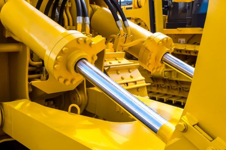
Hydraulic systems are widely used in various fields, from construction and mining machinery to the aerospace industry, from industrial automation to agricultural equipment. These systems are preferred in applications that require high force and precision. Additionally, in the automotive industry, hydraulic systems are utilized in critical components such as brake systems, steering systems, and suspension systems. With these characteristics, hydraulic systems have become an indispensable technology in modern industries.
Overview
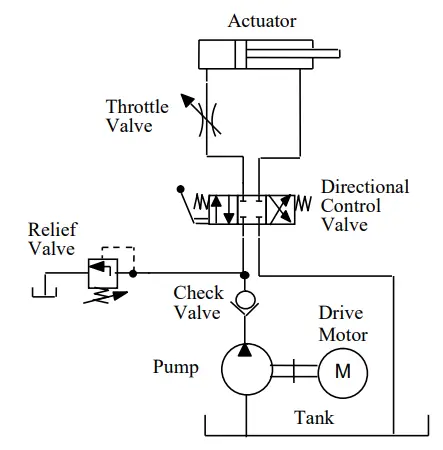
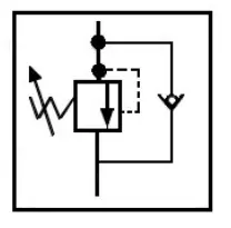
On the side, you can see a simple hydraulic system. Since I will be explaining the functions of the components in this system one by one later, I won’t go into much detail right now. What I want to highlight here is the significant similarity between hydraulic circuits and electronic circuits. While power is transmitted through current in electronic circuits, in hydraulics, the goal is to transmit power by controlling the flow direction, pressure, and flow rate of the fluid. The lines you see in the system represent the main pathways through which the fluid flows. Additionally, you may notice a dashed line leading to the relief valve. This line represents a path where flow cannot occur, symbolizing what is known as a pilot line. It is used to control the pressure in the connected fluid line. As we proceed, I believe you will gain a better understanding of this concept.
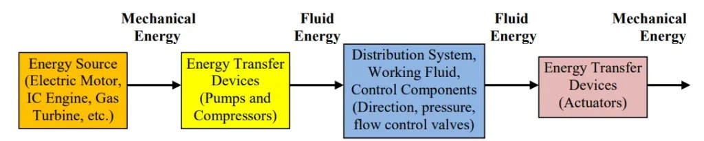
The following illustration helps clarify how a hydraulic system works. As an additional note, the mechanical energy obtained from the electric motor is generated through electrical energy. At this point, I would like to briefly explain how fluid flow is achieved in a hydraulic system. As we know from fluid mechanics, for a fluid to flow, there must be a pressure difference. The system’s control is managed by this pressure difference. In hydraulic systems, the pressurization of a line occurs through the compression of the fluid. Therefore, it is assumed that the fluid is compressible along the line. Now that we have a basic understanding of hydraulic systems, we can move on to introducing hydraulic components.
Pump
In a hydraulic system, the pump is responsible for energy conversion. The mechanical energy from the motor is transferred to the fluid. This mechanical energy is typically transmitted from the motor to the pump via a shaft. In the diagram we used for a general overview of the system, this connection is represented by the shaft. Essentially, the pump is used to generate a flow rate in the fluid. As a result, the line at the pump’s outlet becomes pressurized, which is why it is referred to as the pressure line.
Nonpositive displacement (hydrodynamic) pumps operate by imparting kinetic energy to the fluid, which is later converted into pressure energy. These pumps, such as centrifugal pumps, are best suited for applications where high flow rates and low pressure are required, and they rely on the velocity of the fluid for their operation. Positive displacement (hydrostatic) pumps, on the other hand, move a fixed amount of fluid with each cycle, regardless of the system’s pressure, making them ideal for high-pressure applications. Examples include gear pumps and piston pumps, which maintain a steady flow even as system pressure changes.
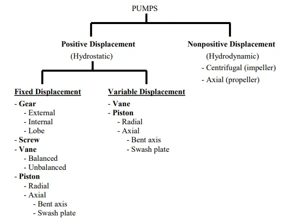
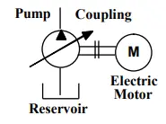
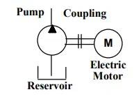
The difference between a fixed displacement pump and a variable displacement pump can be summarized by whether the flow rate is adjustable. A fixed displacement pump generates a constant flow rate throughout its operation. In contrast, a variable displacement pump can adjust the flow rate according to demand (usually based on the error between the desired pressure and the current pressure level). It can be used to prevent the system from becoming underdamped and causing undesirable results. There are different symbols for these two types of pumps. You can see this below. In the case of a variable displacement pump, we see an additional arrow. This arrow symbol is commonly used for all variable components.
Now that we have classified the pumps, we can introduce them. I have provided images below, but I recommend watching videos to better understand how they work. These types of pumps differ in terms of the flow rate they can produce, their efficiency, and cost. Therefore, when deciding on a pump for a hydraulic system, it is important to evaluate all these factors. This will be one of the responsibilities of those of you who plan to work in the field of hydraulics.
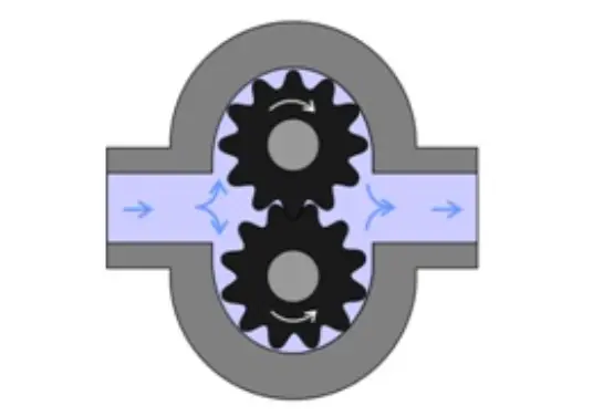
Gear Pump
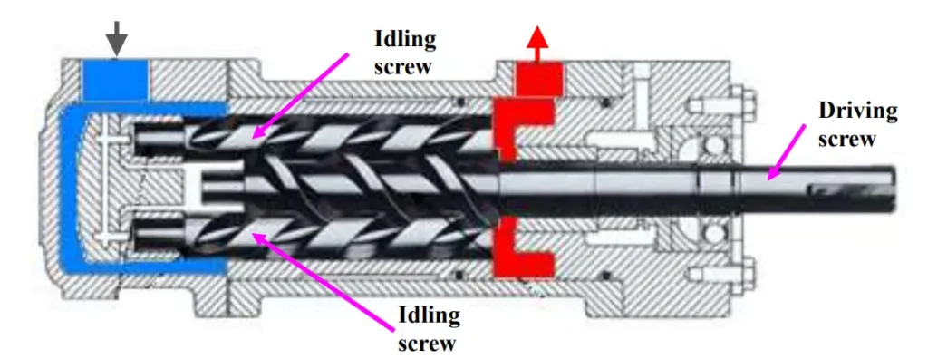
Screw Pump
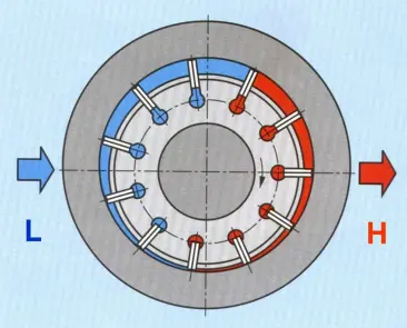
Vane Pump
Unbalanced
Balanced
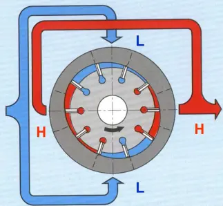
In vane pumps, if there is only one inlet and outlet, the pump becomes unbalanced because the pressure difference between the inlet and outlet creates thrust. To prevent this, a vane pump with two inlets and outlets can be used. However, the disadvantage of these pumps is that they cannot be used as variable displacement pumps.
Piston Pump
Radial
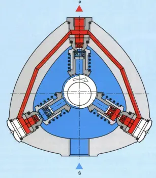
Axial
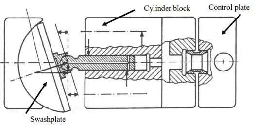
Piston pumps operate based on the principle shown in the photo below. However, to create a constant flow rate in the system, an odd number of pistons is required. Adjusting the angle of the swashplate allows the pump to gain variable flow capability.
Valves
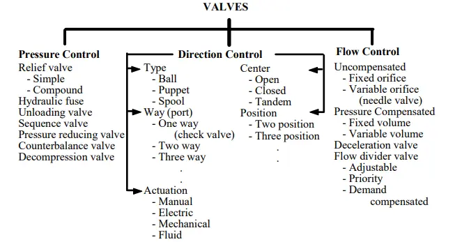
Now, we’ve come to the valves, which are perhaps the most important components of a hydraulic system. The purpose of a hydraulic system is to transmit power through fluids. To achieve this, the fluid must be controlled, and this control is managed through valves. Valves are categorized based on their functions. These functions can be divided into three main categories: pressure control, directional control, and flow control. You can see the visual representation of this classification below.
Pressure Control
Valves used to limit the maximum pressure the system can reach and to reduce pressure are classified under the pressure control valve category. Below are examples of these valves.
Relief Valve
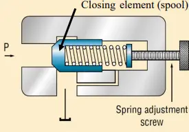
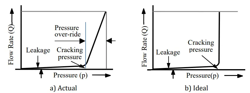
The relief valve is the most well-known and widely used pressure control valve. Its function is to prevent further pressurization in the line when the pressure exceeds the desired value. It achieves this by redirecting the flow from the pump back to the tank. It is typically used as the first component in the pressure line after the pump. The pressure in the line is controlled via a pilot line. If the pressure overcomes the spring force, the flow begins. However, since the valve doesn’t open immediately, the pressure needs to exceed the set value slightly. The designer must ensure that this additional pressure won’t cause damage to the system. The graph below illustrates this factor.
Pressure Reducing Valve
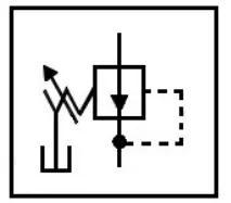
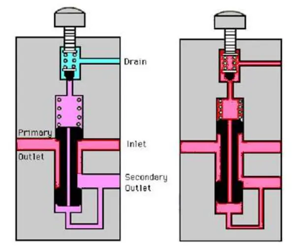
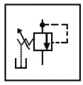
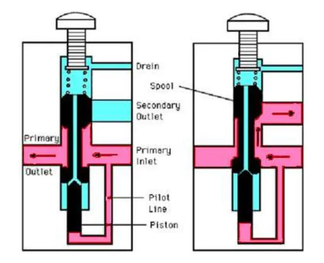
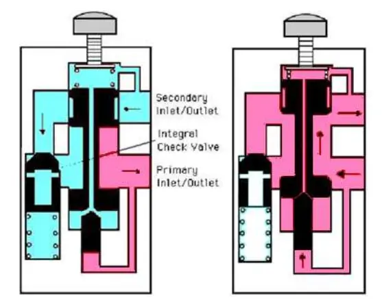
Unlike other pressure valves, the pressure reducing valve is automatically open, as can be seen from its symbol. The primary purpose of the valve is to transfer high input pressure to a lower output pressure. Normally, we would expect the pressure in the output line to eventually equalize with the input pressure. However, with this valve, we can keep the pressure below a certain level.
Sequence Valve
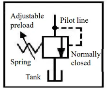
This valve is used to allow flow once the pressure in the line reaches the desired level. The desired pressure is controlled by a spring. When the pressure in the pilot line exceeds this value, the flow moves forward. As can be seen from the diagram, the valve is normally in a closed position.
Unloading Valve
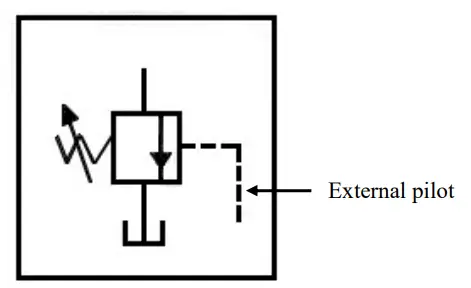
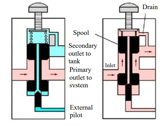
The unloading valve is also normally in a closed position. Although it operates similarly to a sequence valve, in this case, the pressure is measured from an external line rather than internally.
Counterbalance Valve
The counterbalance valve is used to prevent uncontrolled movement under high forces.
Hydraulic Fuse
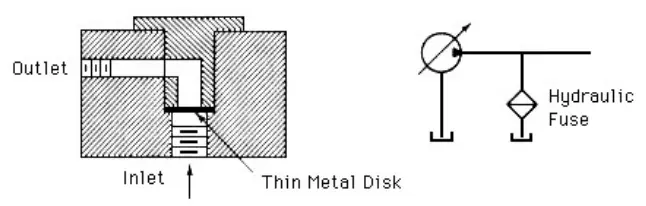
The pressure increase may exceed the level at which the relief valve can respond. In such cases, a hydraulic fuse is used as an additional safety measure. It is placed immediately after the pump in the system and is a single-use component.
Direction Control
Pressure control valves, as we have briefly mentioned, are valves that allow us to control the system based on pressure values. Now, we will move on to valves that allow us to control the direction of the flow. These valves can be broadly divided into two categories: check valves and directional control valves. Below, I will explain these two types of valves in order.
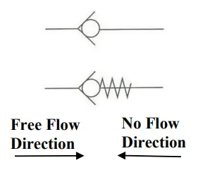
Check Valve
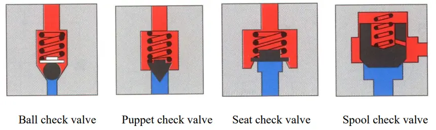
A check valve allows flow in only one direction. When there is an attempt to flow in the reverse direction, a ball blocks the inlet, preventing the flow. It is typically used in the line where the pump is located to prevent reverse flow, thus protecting the pump from damage. Additionally, it is often used in conjunction with various other valves, such as a counterbalance valve. In this case, a spring is used to push the ball towards the inlet. Keep in mind that this valve provides very little resistance and cannot be used like a sequence valve.
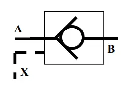
There is another type of check valve known as a pilot check valve. If a pressure signal is sent through the pilot line, the check valve continues to operate according to its normal principles. However, if no signal is sent, the valve allows flow in both directions.
Directional Control Valve
Directional control valves are classified based on their way, position, center position, and actuation. On the side, you can see a directional valve with 4 ways and 3 positions. I will explain the meaning of all these terms using this example.
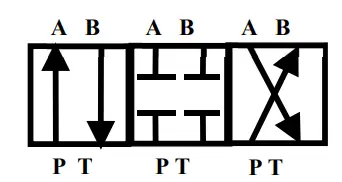
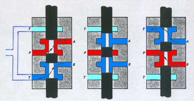
First, the term way represents all the lines the valve can connect to. The A and B labels represent the lines connected to the actuator. From this example, we can understand that a double-acting cylinder is being used. I will cover the details of the actuator later, which should make things clearer. The P label represents the line connected to the pump, and the T label represents the line connected to the tank. Moving on to the positions, as mentioned earlier, there are 3 positions in total. These positions provide details about the task being performed. In the left position, the actuator’s A side is pressurized, causing it to extend, while the fluid from the B side is returned to the tank. In the right position, the opposite action occurs. In the center position, the flow is blocked, holding the actuator in a fixed position. In some projects, the P and T labels are connected to each other in the center position (this is usually preferred when a fixed displacement pump is used). Below, you can better understand how this valve works with the help of a diagram.
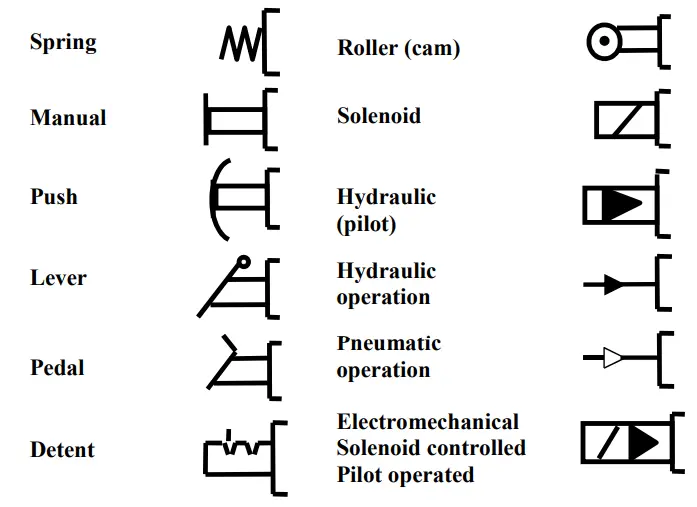
There are various types of actuators available to control a directional control valve. This control can either be manual or automated with the help of sensors and solenoids. On the side, you can see an image showing these actuators. If you want to automate control but avoid using an electronic circuit, a roller actuator can be a suitable choice. It’s important to select an actuator that fits the needs of your system.
As a side note, when modeling a directional valve, it’s also necessary to model the movement of the spool that causes the position change. After all, it’s not physically possible for it to instantly switch between fully open and fully closed positions. Details like the orifice formed during its movement need to be considered. You can learn more about these details in the modeling project we have worked on.
Flow Control
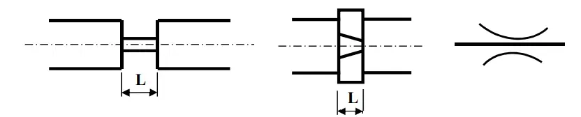
Flow control valves are used to control the flow rate in a system. They can maintain a constant fluid flow despite varying pressure and temperature. The key component of these valves is the orifice, as shown below. The orifice depicted in this image is a fixed orifice. In the adjacent image, you can see a variable orifice, which allows for variable flow rates. Additionally, if a check valve is used alongside the orifice, as shown in the image, the flow can be restricted in one direction while allowing maximum discharge in the reverse direction. Orifices are typically used in the line connected to the actuator. By using a variable orifice and a check valve, the flow rate of fluid entering the actuator can be controlled, while ensuring maximum flow in the opposite direction (to the tank).
Actuators
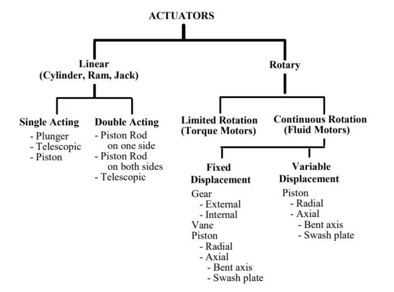
In a hydraulic system, the component responsible for converting fluid energy into mechanical energy is called an actuator. Actuators are divided into two types: linear and rotary. Below, you can see a detailed classification of both types.
Rotary
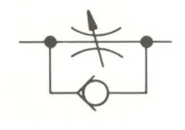
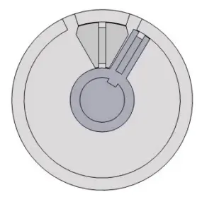
Rotary actuators convert energy into torque. You can think of them as being used to rotate a shaft. Limited rotation actuators, as the name suggests, have a restricted angle of rotation. On the other hand, continuous rotation actuators can continuously transfer a certain amount of torque. In the image beside, you can see an example of a limited rotation actuator.
Linear
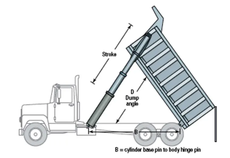
Linear actuators are used to convert fluid energy into linear displacement. Common examples include the brake mechanism on bicycles or the mechanism used to lift the load of trucks. An image of this mechanism can be seen beside.
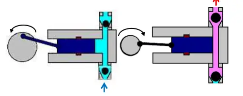
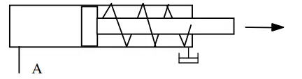
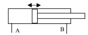
Linear actuators are categorized into two types: single-acting and double-acting. In single-acting actuators, fluid is only applied to one chamber of the piston. To achieve movement in both directions, a spring is typically placed on the opposite side. In double-acting actuators, however, fluid can be applied and released from both sides. The directional valve we discussed earlier is used in such systems. Below, you can see images of both types of actuators. Since both sides can be controlled in double-acting actuators, they offer greater control over the system. However, in single-acting actuators, only one side is controllable, making it harder to achieve the desired movement. But if we only need to control movement in one direction and the reverse direction is not important, single-acting actuators may be preferred due to lower costs or specific requirements.
Other Components
Up to this point, we have discussed the main components of hydraulic systems. In this section, I will cover smaller-scale components such as filters and accumulators. Although the reservoir could also be included in this section, I have chosen not to. However, keep in mind that the reservoir is an important element when designing a hydraulic system. Additionally, when determining the size of the reservoir, don’t overlook details such as ensuring it holds more fluid than what circulates within the system.
Filters
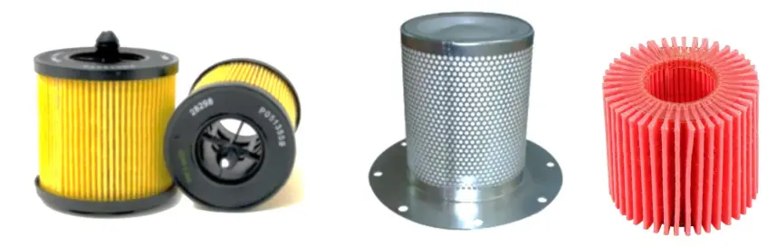
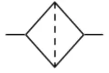
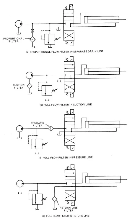
Filters are used to remove solid particles such as metal and dust from the fluid. These particles can gradually wear down and damage system components, making the filter a critical element in hydraulic systems. The position of the filter within the system can vary depending on the specific requirements. In the image beside, you can see alternative locations where filters can be placed. The main disadvantage of filters is that they cause a significant pressure drop in the fluid. If placed before the pump (in the suction line), this pressure drop can lead to cavitation. Therefore, careful analysis is required when positioning the filter in this location. Typically, filters are placed in the return line, so the fluid is cleaned before returning to the reservoir. Filters can also be positioned in the pressure line to protect the actuator from damage. Below, you will find both the symbol for a filter and images of how it looks.
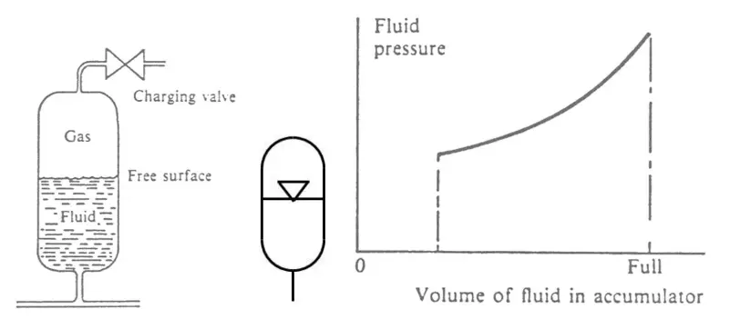
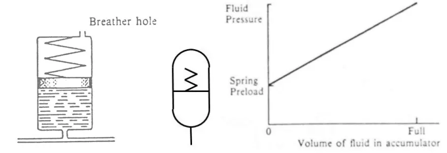
Accumulators
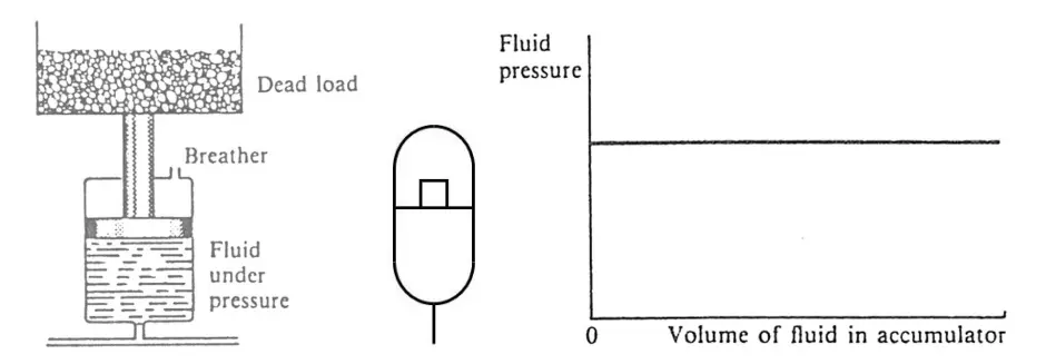
Accumulators are used in hydraulic systems to store energy and release it when needed. They help balance pressure fluctuations in the system and absorb sudden pressure spikes. Additionally, they contribute to energy savings and improve the system’s efficiency. There are different types, such as gravity-type, spring-loaded, and gas-loaded accumulators. Below, you will find the symbols for these three types, as well as a pressure-volume graph illustrating the storage process.
Example
We have now reached the end of what I wanted to explain. I can understand the difference between examining the components individually and analyzing the system as a whole. You might still have a question about how the system operates. For this reason, I’ve decided to conclude this article with an example. There won’t be any numerical calculations, but I will explain how the system works. As an example, I’ll use the most basic system that I mentioned at the beginning of my article. You can see the system in the image beside.
Working Principle
In this system, a fixed displacement pump is used to generate fluid movement. The line following this pump is called the pressure line. The check valve that follows prevents reverse flow towards the pump, protecting it from damage. Next, there is a relief valve, which prevents over-pressurization in the line between the check valve and the directional valve. If the pressure exceeds a certain limit, the fluid is directed back to the tank.
To control the movement of the actuator, a directional valve with 3 ways and 4 positions is used. From the diagram, we can see that the actuator is manually operated. In the center position of the valve, there is no flow, so the piston remains in a fixed position. If the DCV is shifted to the left position, the piston moves to the right. The throttle valve adjusts the flow, allowing us to control the movement. The fluid from the chamber on the right side of the piston is returned to the reservoir. In the right position of the DCV, the piston moves to the left. This is the basic working principle of the system.
Notes and Suggestions
In the system, a throttle valve is used alone. Therefore, when the DCV shifts to the right position, meaning the piston moves to the left, the throttle will restrict the return flow. Since the fluid in the pressure line will continue to be pumped at a constant flow rate, the pressure in the line will eventually exceed the critical pressure value, causing the relief valve to activate and direct the fluid to the tank.
By using a throttle valve together with a check valve, this restriction for the piston moving to the left can be removed. However, this should be planned according to the system’s objectives. If we want to limit both the left and right movements of the system, it would be more ideal to leave it as it is.
Additionally, the need for a throttle can actually be eliminated by using a control system with a solenoid and sensors. Adjusting the movement of the spool can also be achieved by creating an orifice within the DCV, although this is a slightly more complex topic at the moment. The system we design can vary depending on the type of task it is meant to serve. Therefore, it is important to understand which hydraulic systems are used for what kinds of tasks. From this point on, reviewing more examples would be highly beneficial.
Conclusion
In this post, I aimed to share with you what I learned about hydraulic systems during my internship. I briefly explained where hydraulic systems are used, how they work, and their components. Then, with an example, I tried to demonstrate how these components work together as a whole. During the explanation, I also shared a few tips that I came across during my work.
Since this is a new topic for me, I might have written in a somewhat disjointed manner, as if I were taking notes for myself. I apologize for that. If you’re interested in the topic, I believe it would be very beneficial to review the source I referenced below. Additionally, the modeling project I worked on, despite a few mistakes, can be another resource for you to explore.
If you feel confident, I recommend trying to understand the topic by examining the examples. I hope this blog post has been useful for you. Thank you.
References
- Unlusoy, Y. S. ME481 Lecture Notes. Middle East Technical University, Department of Mechanical Engineering.