
Modelling of a Hydraulic System
Simulink
2024
Hydraulic System
Introduction
During the summer internship, we learned a lot about hydraulic system modeling through the books we studied. In the initial stage, we reinforced what we learned by designing a few simple systems on paper. Afterward, we began our modeling project. We created two different models in total. In the first model, we made some assumptions, resulting in an unrealistic model. For the second model, we based our work on various formulas to develop a more realistic model. We also replaced the 3-way 2-position DCV from the first model with a 3-way 3-position DCV and made several corrections.
We had two weeks to prepare both models, and we tried to use this time as effectively as possible. However, due to time constraints, we may have missed some details. I believe we could have produced a more realistic model if we had more time. We completed the project as a team of two, which was quite helpful as we were able to cover each other’s shortcomings throughout the process.
We used Simulink for modeling and BricsCAD for drawings, and we learned how to use both programs during this process. Although I had previously taken courses on Simulink, I hadn’t had the chance to apply it practically before, so this was a great opportunity for me.
The purpose of the model we developed is to position the piston at the desired location. While doing this, we considered the force applied to the piston as a disturbance and prepared a model that is sensitive to different force values. Our system consists of a pump, check valve, directional valve, and actuator in sequence.
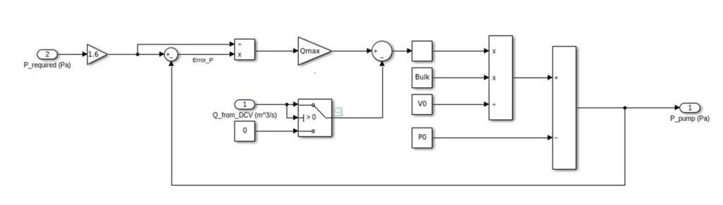
Pump
In this hydraulic system, we chose to use a variable pump. This pump adjusts the flow of fluid proportionally to the difference between the required pressure to keep the piston in the desired position and the current pressure. While modeling the system, we represented the pressure line and the pump within the same subsystem. The fluid entering the pressure line increases the pressure according to the compressibility formula. Similarly, the fluid passing from this line to the piston line reduces the pressure in the pressure line.
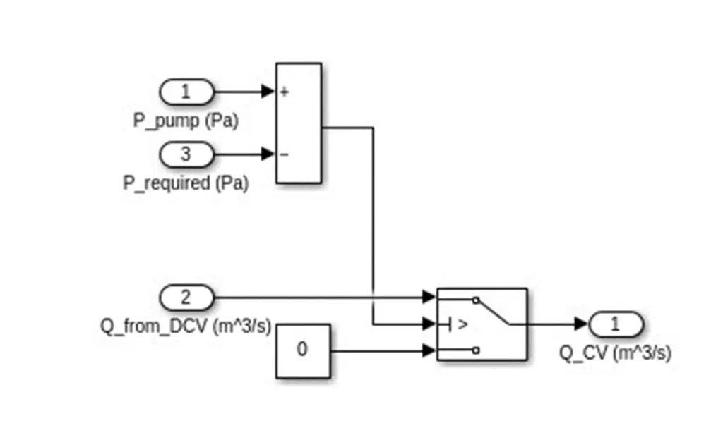
Check Valve
In this system, the check valve prevents reverse flow towards the pump. Additionally, it plays a role in compressing the fluid in the pump line. In a way, it was functioning like a sequence valve. However, we realized during our final presentation that this was an incorrect approach. Although a pressure difference is required for the check valve to operate, these values were too low for our system. It turns out that the check valve could not fulfill the role of a sequence valve.
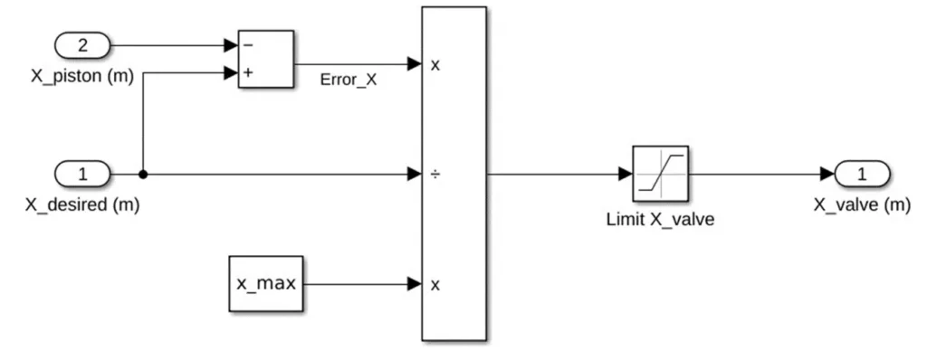
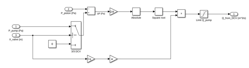
Directional Control Valve
The directional control valve (DCV) is the component we use to direct fluid to the appropriate line of the actuator. In our system, we chose a 3-way 3-position DCV, which is controlled by a solenoid. Our model consists of two subsystems: the spool and the main section. The spool subsystem is where the orifice opening in the DCV is determined. As the error between the desired position and the actual position increases, the opening is adjusted accordingly. In the main subsystem, the orifice equation is used to calculate the flow rate into the piston line based on the position of the DCV.
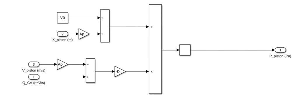
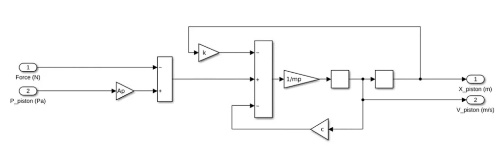
Piston Line and Actuator
The fluid exiting the DCV is directed to the piston line. This fluid not only causes compression and, consequently, pressurization within the piston line, but it also causes the piston to move. Therefore, we can think of this as a moving control volume. In the piston line model, the equations for these two factors are included. In the actuator subsystem, the equations for the piston’s motion are represented.
Conclusion
In this project, I modeled a simple hydraulic system using Simulink. Even though it contains very basic components, I realized that a model can become quite complex. When we wanted to add a new component later on, it could affect other elements in the system differently, and we had to put in a lot of effort to accommodate these effects. We also encountered many details we hadn’t initially noticed. However, for such a short time frame, I believe we developed a well-functioning and mostly accurate model in many aspects.
Below, you can find the slides and the Simulink file we prepared for the project. I hope this project will be helpful for you.